Technology has almost always had a positive impact in everyone’s life. Retail stores have been embracing technology not just to improve the customer experience but also to optimize the operational efficiency and improve the employee work experience. Handheld devices have played a major role in this regard. Be it for inventory management or to help customers checkout items without having to wait in the queue at the register or to function as digital badges for employees, handheld devices play a prominent role in the retail sector. This blog post provides a framework to setup and perform device testing that can help in evaluating the performance on WiFi. However, this piece does not venture into the details of any specific client issues. The post is divided into three sections.
Setting Up the Test Environment
Ideally, any client device testing needs to be performed in production environment where it is intended to be used. If the handhelds are meant to be used inside of store, the testing also have to be performed in an actual store. Some handhelds are designed for outdoor applications. Testing for such devices also needs to be done outdoors accordingly. This is my personal choice for device performance testing. But if that is not feasible, setting up a lab environment that closely replicates the store environment is critical. Most retail companies have mockup stores to demo emerging technologies and such store setup is ideal for a lab. If there are no budget constraints, the entire mockup store can be used as a lab environment. But, that is not always the case. Plan to setup the lab environment with at least four access points. If there are multiple vendor solutions across your retail chain, run multiple cables to each location and install multiple APs next each other (yes, this is bad unless there is only one active network for each iteration of testing). For example, if you have Cisco 2800s in some stores and Mist AP41s in others, you can run two cables to each location and install the APs next to each other. If you would like to test in Cisco environment, you can shut down the Mist APs and vice versa. The AP placement needs to be identical to that of a store environment. If mockup store is not available, then setting up APs in the office and replicating placement in stores would be the last option. In any case, we will require at least four APs.
I will be using the following setup for this blog post purposes.

This is a mockup floor plan with resembling AP placement of a store in production. Notice the channel planning scheme contains one channel from each of U-NII-1, U-NII-2, U-NII-2e and U-NII-3 bands in 5 GHz. The benefit of using four access points with the channel scheme is it would provide insights into the client device’s operational capabilities in each of these bands. Adjust the power levels to be able to produce roaming instances during the process.
Tools and Applications Required
Now that we have a test environment set up, next step would be to identify what features we want to test in the process. One way to determine the device capabilities is going through the association request but a more efficient way is to use the profile application on the WLAN Pi. Instructions on how to use the application can be found here. This application provides client reports of the following format and lists all the capabilities of the devices.
————————————————————
Client capabilities report – Client MAC: #MACHere
(OUI manufacturer lookup: #Namehere)
————————————————————
802.11k Supported
802.11r Supported
802.11v Supported
802.11w Not reported
802.11n Supported (2ss)
802.11ac Supported (2ss), SU BF supported, MU BF not supported
802.11ax_draft Not Supported
Max_Power 22 dBm
Min_Power 8 dBm
Supported_Channels 36, 40, 44, 48, 52, 56, 60, 64, 100, 104, 108, 112, 116, 120, 124, 128, 132, 136, 140, 144, 149, 153, 157, 161, 165
Packet capture tool like Omnipeek or Commview with capabilities of capturing packets on multiple adapters is required. The choice of number of adapters depends on the WLAN. If it is 5 GHz only network, a set of four adapters can be sufficient. If the WLAN is dual-band, a minimum of seven adapters are required. Three adapters will be capturing on each of channels 1, 6 and 11 and the remaining four adapters on channels configured on the APs (36, 64, 100 and 149 in this case). I use Omnipeek with Netgear A6210 adapters.
Multi ping tools like PingPlotter can be very handy to setup continuous pings to the client devices and save data for offline analysis. PingPlotter does a great job of representing ping responses on time axis and traceroute results.
A mobile cart or shopping cart can help in moving the setup from one location to other.
The last of the tools depend on the type of client device being tested. A lot of handheld devices used in retail have Android OS which supports a multitude of WiFi diagnostic apps and logging features. Any diagnostics app like the one below showing RSSI continuously can help in understanding the device performance.

Testing Procedure
After determining the device capabilities from WLAN Pi profiler, we need to identify the WLAN features currently in use. For example, although the client device supports all 802.11k/v/r amendments, all of them may not be enabled on the network. So, it is important to identify the list that we can test and strategize the testing process. Any procedure to evaluate the device performance on WLANs need to be able determine the effectiveness of the following events at a minimum
- Probing
- Authentication
- Association
- 802.1X EAP Exchange (if the WLAN is configured for it)
- 4-Way Handshake
- Power save (depending on the support)
- Roaming – 802.11k/v/r (depending on the support)
While events from probing to 4-way handshake are common to any client device, handheld devices need special attention when it comes to power save and roaming behavior. Every manufacturer has different drivers and these mechanisms determine the device performance on WiFi to a large extent. The process defined below helps in gathering data required to determine this.
- Start at TEST_AP01. Set up Omnipeek with adapters capturing on all 5 GHz channels assigned to the APs along with additional adapters on channels 1,6 and 11 in case of dual band WLANs. Do not configure any mac address based filters for capturing the packets. I recommend using a mobile cart or shopping cart for the laptop setup.
- Connect the client device to the WLAN and note the IP address. Initiate a continuous ping to the client device from PingPlotter.
- Turn off WiFi on client device and initiate packet captures on AP ethernet ports.
- Make sure the adapters are about four to five feet away from the client device to avoid any sideband effects on the capture. Initiate capturing packets on Omnipeek and turn on WiFi adapter on client device.
- Confirm the device received same IP as before and continuous ping on PingPlotter is working.
- Follow a path from one AP to the other similar to the one shown below. Open the diagnostics app if available and keep notes on RSSI values especially when a roam is observed.

- Once you reach back to TEST_AP01 location, stop the continuous ping on PingPlotter and all the captures on Omnipeek and AP ethernet interfaces. Export the files with any naming convention of your choice.
- Repeat the same process without a continuous ping for iteration 2. This iteration is to collect data when the device does not have active traffic.
At the end of both iterations, we have gathered most of the data required for analysis that can help in determining the client device behavior in multiple aspects like
- Probing behavior of client device (sequential, preference of non DFS vs DFS, selective when using 802.11k)
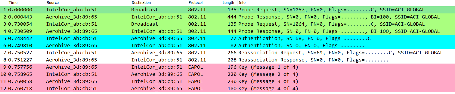
- Association, Authentication, Re Association and 4 Way handshake
- 802.1X process from captures on Omnipeek along with AP ethernet interfaces
- Band preference (2.4 GHz vs 5 GHz)
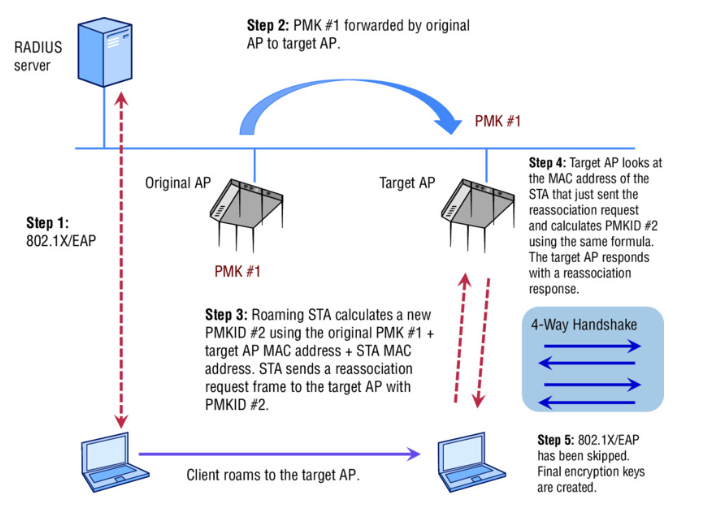
- Roaming performance between channels belonging to U-NII-1, U-NII-2 , U-NII-2e and U-NII-3 bands
- Device power save behavior (with traffic in iteration 1 vs without traffic in iteration 2)
- RSSI thresholds at which roaming occurred from the diagnostics tool. In the absence of such tools, RSSI values on Omnipeek can help in estimating the threshold to initiate probing to roam.
- Ping losses and timestamps from PingPlotter to correlate with roaming instances or to detect power save issues.
The tools required and guidelines provided are intended to help evaluate the device performance with minimum inventory in the best way possible. Having more access points and more adapters for packet captures will certainly help in gathering more data which will be very useful for analysis.